
print the number of seconds since reset:ĭownload the above code to the controller board and see the result.

(note: line 1 is the second row, since counting begins with 0): set up the LCD's number of columns and rows: initialize the library with the numbers of the interface pins This example code is in the public domain. This sketch prints "Hello World!" to the LCD There are many of them out there, and youĬan usually tell them by the 16-pin interface. Library works with all LCD displays that are compatible with the Please make the change in your program before you try compiling it.ĭemonstrates the use a 16x2 LCD display. Int DB = // use array to select pin for bus Let’s have a look at the code for the tutorial. You will find fritzing diagrams below outlining circuit connections for both the Arduino Uno and the Arduino Mega 2560. Hardware Required : Here’s the hardware you will need for the tutorials – According to the product manual, it has two connection methods, namely 8-bit connection and 4-bit connection.
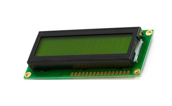
BLA is anode for back light BLK, cathode for back light.ġ602 can directly communicate with Arduino. 
D0-D7 is 8-bit bidirectional parallel bus, used for command and data transmission. When this pin is in high level, the bus is not allowed to have any change. Usually, when the signal in the bus is stabilized, it sends out a positive pulse requiring read operation. When the pin is in high level, it’s in read operation when it’s in low level, it’s in write operation. When the pin is in high level, it’s in data mode when it’s in low level, it’s in command mode. Here, we use low potential method connect the resistor and then the GND. For the connection, it has 2 methods, namely high potential and low potential. In this experiment, we use a 1KΩ resistor. VL is the pin for adjusting contrast ratio it usually connects a potentiometer(no more than 5KΩ) in series for its adjustment. In this project, we use 3.3V for backlight. Two power sources, one for module power, another one for backlight, generally use 5V. Optimum working voltage of the module is 5.0V. Now, almost all 1602 LCD module uses a compatible IC, but their features are basically the same. In the beginning,1602 LCD uses a HD44780 controller. In this experiment, we use an Arduino to drive the 1602 LCD. Once you’ve sorted all of the above you are ready to move onto the next tutorial. If you haven’t installed the Arduino IDE please head back to the first tutorial and make sure you’ve gone through each of the steps involved. Blink LED’s) example programs (that comes with the Arduino IDE) onto your Arduino UNO board Have been successful in uploading a simple (e.g. Are able to connect to the Arduino IDE from your computer. Downloaded and installed the Arduino IDE. Before you start working with any of the tutorials in this series please make sure you have completed the following tasks –.


 0 kommentar(er)
